The systems engineering process begins with an information gathering and organizing function. Complex systems have functional, spatial and temporal aspects that cannot all be considered at the same time. Therefore several techniques are required to view the various aspects of a system in order to effectively specify its form and function. No view is most important or necessarily the first to be developed.
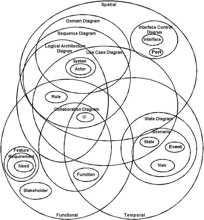
The following diagram illustrates how many of the concepts and views overlap. Do not worry. You will never otherwise have to try to view all theses ideas at once.

Here are some of the activities associated with requirements analysis. Many terms are defined during the course of system development. These terms are categorized according to their relationship to the system. The systems engineer insists that all terms associated with a project be precisely defined and that appropriate diagrams are maintained. The following table identifies many of the terms and types of diagrams that may be employed to concisely describe a system
| What are the components | Spatial Diagrams | How do the components interact | Functional Diagrams | When do interactions take place | Temporal Diagrams |
|---|---|---|---|---|---|
| Systems are collections of components or subsystems. These can be logical or physical. The Subject System is decomposed into Logical Systems that are interesting to the systems engineer as they allow extensive specification without concern as to how or with what technologies a system will be implemented | Domain Diagrams show all of the existing related systems | Stakeholders know what the system needs to do. Stakeholders are defined by the role they play with a system | Collaboration Diagrams show the functional interactions among system components | States define the principal situations that a system can be designed to tolerate | Use Case Diagrams illustrate the actors and their uses of a principal interactions with a system |
| Roles are the part of a system that provide functions to an interaction | Logical Architecture Diagrams show the logical internal components of a system. | Needs imprecisely describe what a system must do. These are captured from stakeholders and are traced to formal requirements | Interface Control Documents define the I/O related to an Interface | Functions can be expressed as procedures that respond to situations | State Diagrams identify all situations a system can exist in and the transitions among those states. |
| Functions are allocated to physical components | Physical Architecture Diagrams show the actual internal components of a system | Features are precisely defined collections requirements that provide system value | Interactions describe the interplay of systems effecting each others state | Sequence Diagrams show the temporal relationships among systems. They are slices through the state diagram. | |
| An Actor is a system not part of the system being described. It interacts with the subject system | Requirements are formal unambiguous, concise statements of system needs. | Events signal the transition of a system from one state to another | Story Boards pictorially describe paths through system states. They are equivalent to sequence diagrams for human actors | ||
| Interfaces are collections of Inputs and outputs (I/O) for a specific purpose. | Functions are descriptions of the part of an interaction played by a role | Transitions define anticipated state changes. | |||
| Ports provide for the sending and receiving of I/O | I/O is information, mass or energy that passes from one system to another. |
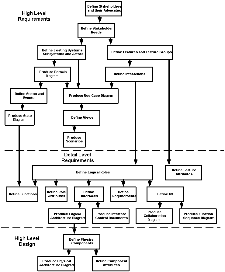
The following diagram illustrates how each artifact depends on others. While any combination of artifacts can be worked on, one cannot be said to be complete unless it is audited to artifacts on which it depends.
 The system engineering process is next to impossible without a methodology to guide an SE through the maze that finally arrives at a comprehensive architecture.
Back | Next | Requirements